Arduino light-gates
http://tiny.cc/EMSarduino
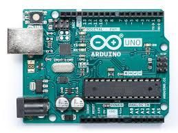
What is Arduino?
Open-source electronics platform
Arduino boards are able to read inputs - light on a sensor, a finger on a button, or a Twitter message - and turn it into an output - activating a motor, turning on an LED, publishing something online.
You can tell your board what to do by sending a set of instructions to the microcontroller on the board.
To do so you use the Arduino programming language (based on Wiring), and the Arduino Softwarehttps://www.arduino.cc/en/Main/Software(IDE), based on Processing.
Over the years Arduino has been the brain of thousands of projects, from everyday objects to complex scientific instruments. A worldwide community of makers - students, hobbyists, artists, programmers, and professionals - has gathered around this open-source platform, their contributions have added up to an incredible amount of accessible knowledge that can be of great help to novices and experts alike.
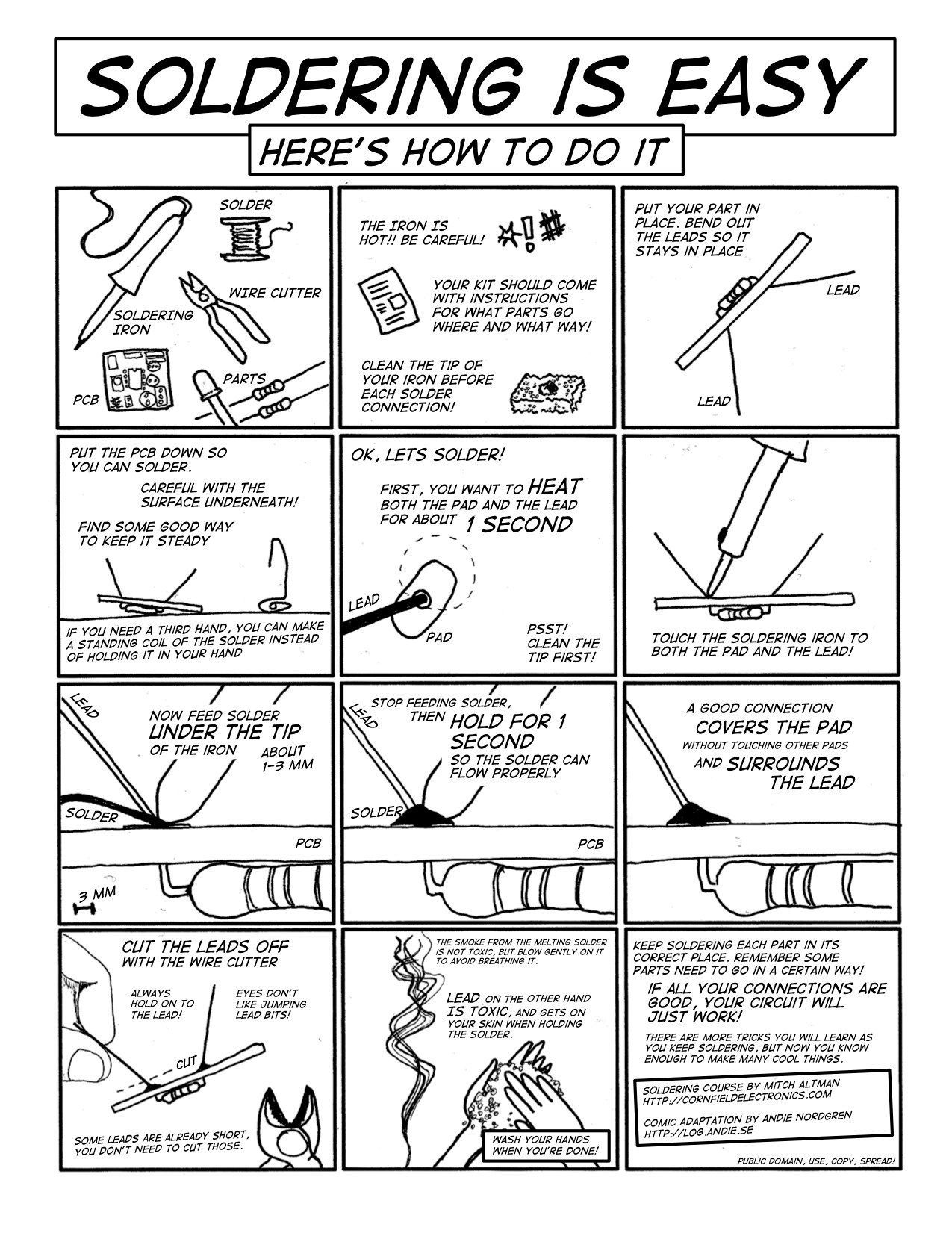
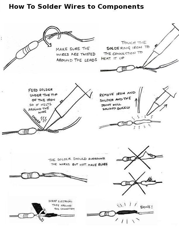
Soldering
What is a Light Gate?
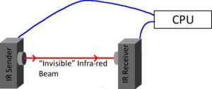
A light gate has a beam going from one LED/IR light source onto a detector. As something goes through it, the beam is “Cut”.
The light gate measures how long the beam has been cut for.
Some light gates will allow you to plug in the length of the crossing object, and then it an automatically calculate acceleration etc.
Our Light Gate
https://www.xtronical.com/projects/light-gate/building-light-gate-measuring-speed/
Parts List
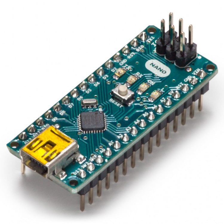
MCU : 1 x Arduino Nano
IR Receiver : 1 x TSOP38236 (or any TSOP382xx series should be fine.
IR Sender : Any Infra-Red LED at around 940nm (940nm is the particular wavelength of infra red we are using, but anything around this should be OK).
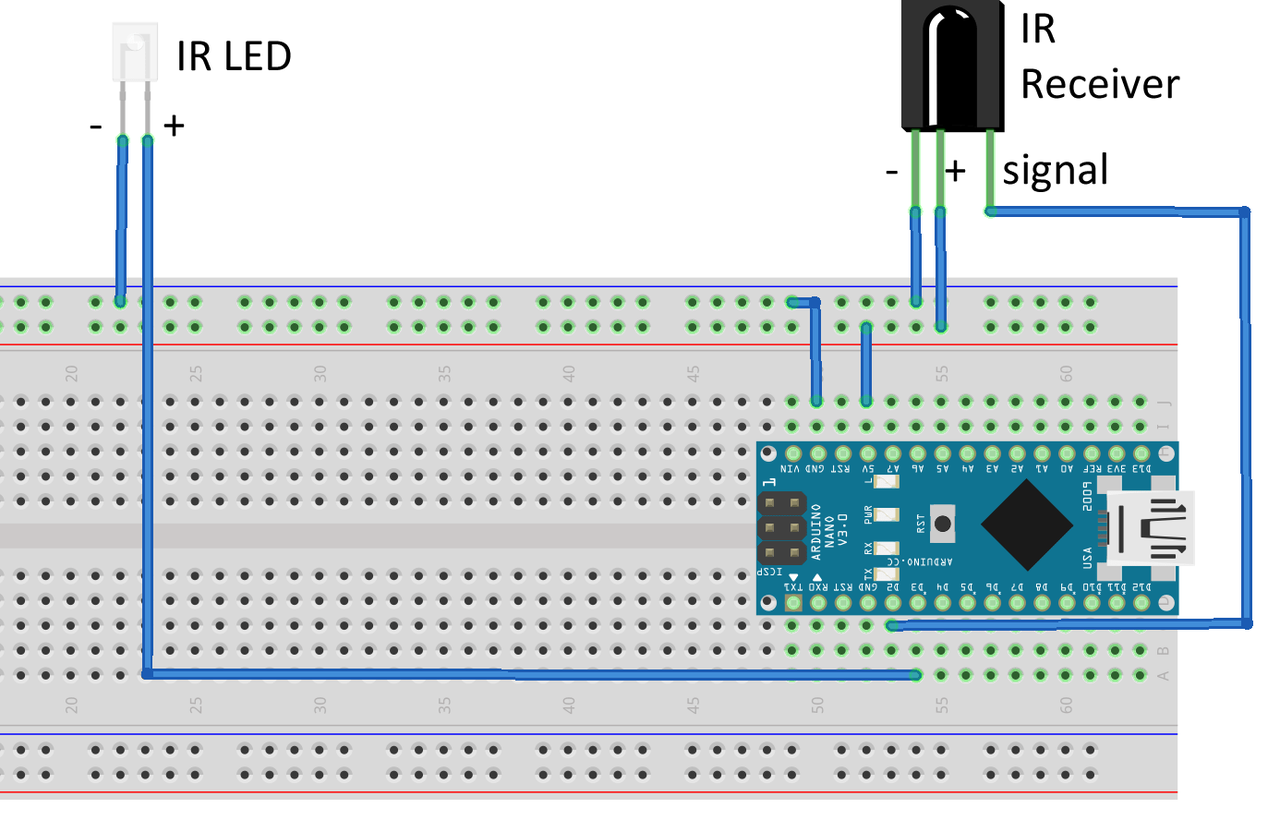
Connection Table
|
|
|---|---|
|
|
|
|
|
|
|
|
|
|
Why no LED resistor?
Use Sketch 1 to test your board
To use the test code below you will need to ensure you have the IRremote library installed. You can do this from within the Arduino IDE by simply clicking on “Sketch->Include Library->Manage Libraries”. In the search box type “IRRemote” and the library will appear. Click install and your done! Load up the code below onto your Nano (or whatever board you have used) Remembering to change line 12 to whatever frequency you are using if you are not using a 36Khz sensitive receiver.
#include <IRremote.h>
#define PIN_IR 3
#define PIN_DETECT 2
#define PIN_STATUS 13
IRsend irsend;
void setup()
{
pinMode(PIN_DETECT, INPUT);
pinMode(PIN_STATUS, OUTPUT);
irsend.enableIROut(36);
irsend.mark(0);
delay(1000); // wait for system to settle
}
void loop() {
digitalWrite(PIN_STATUS,digitalRead(PIN_DETECT));
}
If all goes well you will note that the on board LED connected to pin 13 on the Nano lights up when there is no IR signal and goes out when there is, it’s inverse logic, off when there’s an IR beam, on when there isn’t.
Measuring Speed
Why use a Light-Gate?
So in essence all we need to do (if we were measuring someones speed at a sports day for example) would be to start a stop watch when they start running and stop it when the cross the finishing line. We know how far they’ve run (say 100m) and we now know how long it took them, so we can calculate a speed. But there is some inaccuracy to that system due to the human pressing the stopwatch. For a children’s sports day over a 100m it’s probably not that important but if we want to measure objects over a much shorter distance — say a few cm’s — then those human reaction times make accurate results almost impossible. We need something with extremely fast reaction times and able to time to hundreds if not thousands of a second. This is where a Light-Gate comes in. Electronics have a much better reaction time than humans and can count time to incredibly small amounts, perfect for out uses.
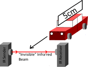
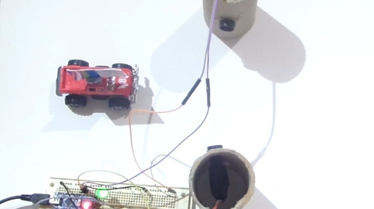
Using our gate:
We have stuck a piece of thin card on top of the car which we know the length of, in this case 5cm. Obviously the card must be the only thing to pass the beam, so the beam must be higher than the car body. When the card first cuts the beam we start our timer, when the card clears the beam we stop our timer. In that time the car has travelled the length of the card, in this case 5cm. So we know how far it’s travelled and the time it’s done it in, we can calculate a speed. And we did this with only one light gate.
The code below will perform the speed calculation for you reporting it back in the serial monitor. Note your card length must be 5cm, if you want anything different then alter the #define at the start of the code to whatever your card length is.
#include <IRremote.h>
// card length in cm
float CardLength=5;
#define PIN_IR 3
#define PIN_DETECT 2
#define PIN_STATUS 13
IRsend irsend;
void setup()
{
pinMode(PIN_DETECT, INPUT);
pinMode(PIN_STATUS, OUTPUT);
irsend.enableIROut(36);
irsend.mark(0);
Serial.begin(9600);
delay(1000); // wait for system to settle
}
void loop() {
// wait for active
digitalWrite(PIN_STATUS,false);
while(digitalRead(PIN_DETECT)==true);
digitalWrite(PIN_STATUS,true);
// wait for “thing” to cross beam
while(digitalRead(PIN_DETECT)==false);
// start timing
digitalWrite(PIN_STATUS,false);
long int StartTime=millis();
// wait for thing to stop blocking beam
while(digitalRead(PIN_DETECT)==true);
// end timing
long int EndTime=millis();
long int TotalTime=EndTime-StartTime;
float Secs=float(TotalTime)/1000;
float Speed=CardLength/Secs;
Serial.print(Speed);
Serial.println(“cm/s”);
Speed=(CardLength/100)/Secs;
Serial.print(Speed);
Serial.println(“m/s”);
}
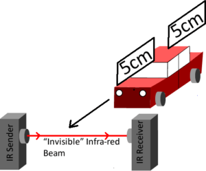
Measuring acceleration
Instead of having two light gates we have two pieces of card (same length) on top of our car (or whatever moving object) a small distance apart. As we have a very accurate timekeeper accurate to 1 thousand of a second this is a very valid way of doing this. If the object under test was travelling very very fast then two light gates may be required but unlikely in the scenario of what is being built. Below is a diagram of how it might appear:
Here’s the code:
#include <IRremote.h>
float LengthOfCard=0.05;
#define PIN_IR 3
#define PIN_DETECT 2
#define PIN_STATUS 13
IRsend irsend;
void setup()
{
pinMode(PIN_DETECT, INPUT);
pinMode(PIN_STATUS, OUTPUT);
irsend.enableIROut(36);
irsend.mark(0);
Serial.begin(9600);
delay(1000); // wait for system to settle
}
float WaitForSpeedReading()
{
/// returns a speed reading
// wait for active
digitalWrite(PIN_STATUS,false);
while(digitalRead(PIN_DETECT)==true);
digitalWrite(PIN_STATUS,true);
// wait for “thing” to cross beam
while(digitalRead(PIN_DETECT)==false);
// start timing
digitalWrite(PIN_STATUS,false);
long int StartTime=millis();
// wait for thing to stop blocking beam
while(digitalRead(PIN_DETECT)==true);
// end timing
long int EndTime=millis();
long int TotalTime=EndTime-StartTime;
float Secs=float(TotalTime)/1000;
return LengthOfCard/Secs;
}
void loop() {
float Speed1,Speed2;
Speed1=WaitForSpeedReading();
// for accel it’s the change in speed over a time period, so after measuring
// the first speed we record start time that this speed was recorded at
// then after the second speed measurement we do the same again and then record
// the time between these speed changes
long int StartTime=millis();
Speed2=WaitForSpeedReading();
// record end time
long int EndTime=millis();
// get the time between both speed readings and convert to seconds
float TimeTaken=(float(EndTime-StartTime)/1000);
// equation for acceleration is
// accel=EndSpeed-StartSpeed/Time Taken for that change
float accel=float((Speed2-Speed1)/TimeTaken);
Serial.print(“Start Speed “);
Serial.print(Speed1);
Serial.print(“m/s , “);
Serial.print(“End Speed “);
Serial.print(Speed2);
Serial.print(“m/s , “);
Serial.print(“Time Taken : “);
Serial.print(TimeTaken);
Serial.println(“s”);
Serial.print(“Acceleration = “);
Serial.print(accel);
Serial.println(“m/s2”);
}
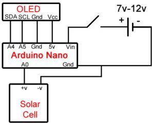
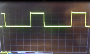
Strobe light Frequency Meter
The code to make this work is shown below, it simply looks for the rising edge of the voltage from the solar cell, records the value of the timer in milliseconds then waits for the next rising edge. When it gets the next rising edge it means we have gone through one complete wave and it looks at the timer again. It works out the difference in time between the start of the wave and end (in milliseconds) and then does a quick calculation to give this value in Hz. In reality if you look closely it actually does an average of 20 values by default then calculates the average Frequency.
#include <Adafruit_GFX.h>
#include <Adafruit_SSD1306.h>
#define RisingEdgeLimit 200
#define IncrementToProveRisingEdge 50
#define DecrementToProveFallingEdge 30
#define NumberOfResultsToAverage 20
uint32_t LastTime;
uint32_t ThisTime;
uint32_t Reading;
float Frequency=0;
uint8_t AvgCounter;
float Average;
Adafruit_SSD1306 display(4);
void setup() {
// put your setup code here, to run once:
display.begin(SSD1306_SWITCHCAPVCC, 0x3C); // initialize with the I2C addr 0x3C (for the 128x32)
Reading=analogRead(A0);
LastTime=millis();
AvgCounter=0;
Average=0;
display.clearDisplay();
display.setCursor(0,0);
display.setTextSize(2);
display.setTextColor(WHITE);
display.print(“Waiting”);
display.display();
}
void loop() {
// Take a reading, check and change threshholds if required
while(Reading<RisingEdgeLimit) // wait for rising edge
Reading=analogRead(A0);
while(Reading<RisingEdgeLimit+IncrementToProveRisingEdge) // confirm rising edge
Reading=analogRead(A0);
// calculate a frequency
ThisTime=millis();
Frequency=1000/float(ThisTime-LastTime);
LastTime=ThisTime;
Average+=Frequency;
AvgCounter++;
if(AvgCounter==NumberOfResultsToAverage)
{
DisplayResult(Average/NumberOfResultsToAverage);
AvgCounter=0;
Average=0;
}
while(Reading>RisingEdgeLimit) // wait for dropping edge
Reading=analogRead(A0);
while(Reading>RisingEdgeLimit-DecrementToProveFallingEdge) // confirm dropping edge
Reading=analogRead(A0);
}
void DisplayResult(uint16_t Freq)
{
display.clearDisplay();
display.setCursor(0,-1);
display.setTextSize(5);
display.setTextColor(WHITE);
display.print(Freq);
display.setCursor(display.getCursorX(),11);
display.setTextSize(3);
display.print(“Hz”);
display.display();
}
If you look at the start of the code you will also need two supporting files for driving OLED screens from Adafruit. You can install these from your Arduino IDE, go to the menu “Sketch->Include Library->Manage Libraries”. Type “adafruit ssd1306” into the search and you should get the 1306 OLED library. Select and click install. Then type “adafruit gfx” into the search and install the library also.
Files:
https://www.dropbox.com/sh/rf4wlecitn2cr15/AACU4ElDXBO0XiSzSxWlwvH8a?dl=0?dl=0