An introduction to…Resistance in a Metal Wire
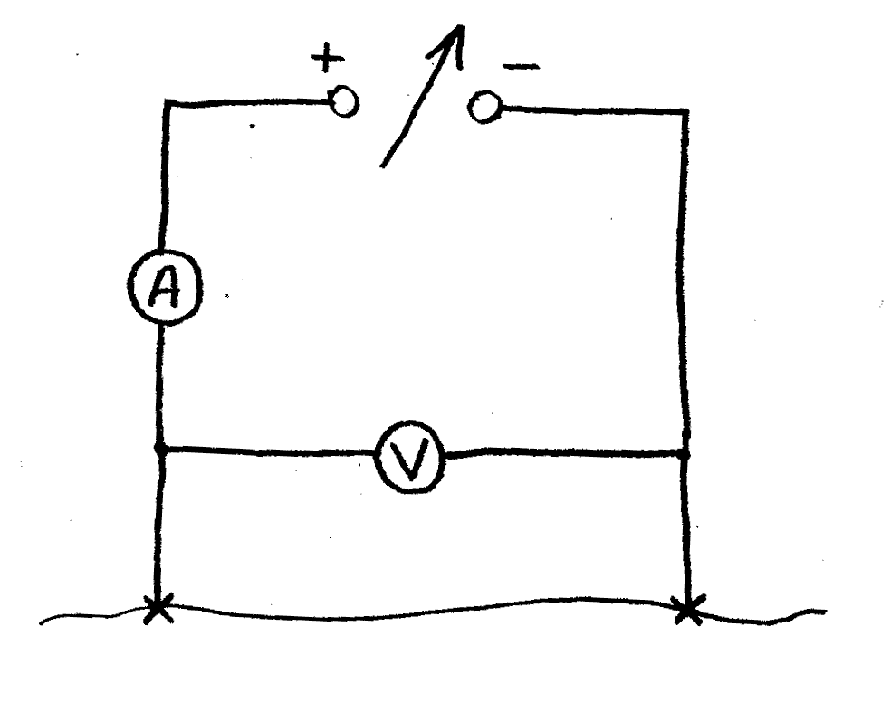
Set up the circuit as shown in the diagram below, with a length of constantan wire held between crocodile clips. Make sure that the bare wire does not touch any other part of the circuit. Ammeter and voltmeter are each digital multimeters (DMMs) set to the 2A dc and 2V dc ranges respectively.
Start with the supply voltage at 0V. Gradually increase the supply voltage to give a suitable pair of readings of current and voltage. Do not exceed either 1A or 1V, otherwise overheating may occur.
Measure the length of wire between the crocodile clips (l), the voltage across the wire (V) and the current through the wire (I). Calculate the value of resistance (R1) for this length of wire. Record your results in an appropriate table.
Adjust the power supply to give you a different pair of voltage and current readings (still less than 1V and 1A) for the same length of wire. Calculate the resistance (R2) and hence the average resistance (R) for this length of wire.
Reduce the power supply voltage to zero and move the crocodile clips to give you a different length of wire in the circuit.
Repeat measurements for a further five values of l in the range 20cm to 100cm.
Plot a graph of resistance against length and determine the gradient of the best-fit straight line in ohms per metre.
Use the micrometer to determine the diameter of the wire and hence calculate the crosssectional area of the wire in square metres. Given that the resistivity is equal to the gradient of your graph multiplied by the cross-sectional area, calculate the resistivity of constantan and compare to a value from a data book or other reference.
Apparatus:
Power supply (variable)
DMM Yellow (as Voltmeter)
DMM 318 (as Ammeter)
1.1m length 26swg Constantan wire
Metre rule
Micrometer (shared)
Leads (×5)
Crocodile clips (×2)